[17-NOV-10] Our original A3015A loop antenna had no attenuator between the antenna and the coaxial cable. This antenna perfomed well out in the open, but reception was intermittent when we used it inside faraday cages. It took us a year to identify the cause of poor reception, but when we did so, our observations were repeatable and compelling.
We had been going into the OSI office every morning to work for an hour on intermittent data corruption and reception problems. One this particular morning, we arranged the cables and observed poor reception from the faraday cage. We exchanged the data receiver, moved the transmitter within the cage, re-seated the cage lid, and removed the antenna combiner, but always we observed poor reception from within the cage. We began a series of experiments with coaxial attenuators, which we can insert into the antenna system at any BNC junction.
| Configuration | Reception |
|---|---|
| antenna-coax-wall-coax-receiver | 81% |
| antenna-coax-wall-coax-2dB-receiver | 97% |
| antenna-coax-wall-coax-3dB-receiver | 99.6% |
| antenna-coax-wall-coax-6dB-receiver | 99.0% |
| antenna-coax-wall-coax-8dB-receiver | 99.8% |
| antenna-coax-wall-coax-9dB-receiver | 100% |
| antenna-coax-wall-coax-receiver | 84% |
| antenna-coax-wall-3db-coax-receiver | 100% |
| antenna-coax-wall-coax-receiver | 86% |
| antenna-coax-wall-2db-coax-receiver | 100% |
| antenna-coax-wall-3db-coax-receiver | 100% |
| antenna-coax-wall-6db-coax-receiver | 100% |
| FE2B Lid Off, antenna-coax-wall-coax-receiver | 69% |
| FE2B Lid Off, antenna-coax-wall-3dB-coax-receiver | 94% |
| FE2B Lid Off, antenna-3dB-coax-wall-coax-receiver | 94% |
| antenna-3dB-coax-wall-coax-receiver | 100% |
| antenna-coax-wall-coax-receiver | 88% |
| antenna-3dB-coax-wall-coax-combiner-receiver Empty FE2A, antenna-6dB-coax-wall-coax-combiner-receiver | 100% |
| Transmitter in Open, antenna-3dB-coax-combiner-receiver | 59% |
These results convinced us that we should add an attenuator to the A3015 circuit board. We see that 3 dB is always adequate. Any larger attenuation would weaken our signal without any benefit from better impedance matching.
[14-DEC-12] We purchased ten 1.8-m RG-58/U BNC cables from Jameco, part number 205-527BK. We connected five of these together to make one 9-m cable. We applied +22.0 dBm (8 V p-p) of 146 MHz from our Command Transmitter (A3023) to one end, as measured by our 300-MHz oscilloscope. The signal at the other end was 18.5 dBm (5.3 V p-p). We lose 0.39 dB/m, which is three times the 0.11 dB/m we expect for RG-58/U from our table of cable properties. We replace the 205-527BK with 1.8 m of our Amphenol RG-58C/U and get 20.9 dBm out the other end, for 0.12 dB/m, which is slightly less than the 0.16 dB/m we expect for this type of cable.
[19-FEB-16] An antenna that detects transmitters only up to ranges of one or two centimeters would be useful as part of an animal tracking system. A video camera above the animal cage can monitor movements of blobs, each blob being one or more animals moving or resting together. When a blob is near the short-range antenna, we receive data from the transmitters implanted in the animals, and so we can identify which animals are in the blob. We took an A3015B and cut the wire back until it was a loop of diameter 10 mm. We measure reception versus range with three different attenuators placed in series with the antenna cable. All measurements are within an FE2F faraday enclosure. In our first test, we place the transmitter in 50 ml of water to simulate imlantation in a 50-g rodent. The antenna is vertical.
Reception does not always increase as range decreases: reception dead spots cause drops in reception even when the transmitter is near. We pour the water out of our 50-ml beaker and repeat, making sure the transmitter is still standing up and oriented identically.

[20-AUG-19] When our transmitters are operating within an aquatic chamber, we use shorter antennas to receive their signals. We applied +0 dbm of 915 MHz to an A3015C antenna vertical on our bench top and measured the power received by various antennas in air and water using our handheld spectrum analyzer.

We summarize our measurements in the table below.
| Antenna | Orientation | Power In Air (dB) | Power Water (dB) |
|---|---|---|---|
| BNC Plug Only | Vertical | −70 | −57 |
| A3015C Damped Loop | Vertical | −27 | NA |
| A3015D Aquatic Loop | Vertical | −32 | −39 |
| A3015D Aquatic Loop | All | −41..−54 | −38..−51 |
| 20-mm Whip | Vertical | −55 | −40 |
| 20-mm Whip | Horizontal | −46 | −54 |
| 50-mm Stiff Loop | Vertical | −41 | −42 |
| 50-mm Stiff Loop | All | −38..−43 | −41..−48 |
The Aquatic Loop (A3015D) placed in a beaker of water gives us robust reception of transmission from an A3028E at range 30 cm in a Faraday Enclosure. When operating in an aquatic chamber to receive signals from an aquatic animal, we recommend the A3015D.
[06-DEC-21] We have performed quality control on the A3015C in many ways over the years, but today's test is as described by Nathan Sayer. "My process for testing antennas went as follows. I hung the antenna being tested in front of one of the absorbers with no attenuators attached to the cable. I then moved a transmitter all around the enclosure and made sure that I saw around 75% reception. Then, I attached a 30dB attenuator to the antenna being tested and made sure that it got reception when the transmitter was close to the antenna. The transmitter had to be within maybe 15cm (estimate) in order to get reception with the 30dB attenuator attached."
[14-MAR-22] We place an A3015C loop antenna on center of the floor of an FE2A enclosure. We support another A3015C antenna outside the enclosure, in front of the door, at a range of 100 cm from the first antenna. We connect +10 dBm to the external antenna through 2 m of coaxial cable. The two antenna are facing one another. The internal antenna is upright, as defined by its mounting brackets. At first, the external antenna is at 90° to the internal. The internal antenna we connect to the back wall of the enclosure, and then to our hand-held spectrometer. We apply 400-3000 MHz and for each frequency measure power received by the internal antenna with the FE2A door open. We repeat with the external antenna at 0° (also upright).

In the 900-930 MHz band we see −27 dBm with the antennas aligned, and as little as −40 dB with them un-aligned by 90°. This difference of 12 dB suggests that the A3015C efficiency perpendicular to its face varies by 6 dB as we rotate about the axis of the loop. At its best, we see −25 dBm at the receiving antenna. Given that we have a 3-dB attenuator in both antennas, we have at most 7 dBm radiated by the external loop and at least −22 dBm at the receiving loop. We are receiving 1/800 of the power transmitted. The effective area of our receiving antenna is of order 1/800 of 13 square meters = 12 cm diameter, which is roughly the diameter of the A3015C.
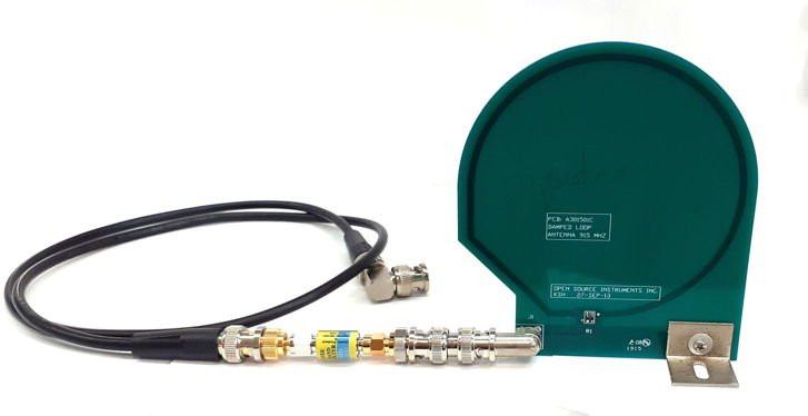
[17-MAR-22] We construct the following prototype Filtering Loop Antenna out of an A3015C, a CBPFS-0915 in-line filter, SMA-BNC adaptors, a 1-m RG58C cable, and a BNC elbow.
[21-MAR-22] We compare the filtering loop antenna to the damped loop antenna in our Faraday canopy. Nathan writes, "I ran some tests comparing the loop antenna performance with and without the saw band pass filter. I found that on both the ODR and the TCB the saw band pass filter being connected to the loop antenna made no difference in reception." At Marsaille, where we are suffering from a 1 kW LTE base station ten meters away on the roof, which transmits in 1850-1910 Mz as well as 832-862 MHz. We find that the Damped Loop Antenna attached to an Animal Location Tracker's auxiliary input provides dramatically improved reception compared to the coil array alone. Reception rises to 97% in one enclosure and 92% in another. When we switch to the Filtering Loop Antenna, by inserting the CBPFS-0915 in the antenna cable, reception improves further to 98% and 94%.