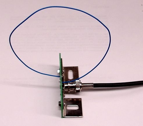
[10-MAR-25] The Loop Antenna (A3015) is designed to receive signals from our small-animal telemetry sensors. These sensors use the 902-928 MHz Industrial, Scientific, and Medical (ISM) band, so the A3015 antennas are designed to be most sensitive to radio waves in this range.
We use these same antennas to transmit commands to our Implantable Stimulators. The Telemetry Control Box (TCB-B16), for example, provides sixteen antenna inputs. Each antenna input has its own independent telemetry receiver, but also a command transmitter. The antennas spend almost all their time receiving telemetry signals, but occasionally the TCB-B16 will commandeer the antennas for command transmission.
Most radio-frequency antennas are designed to maximize sensitivity in their most sensitive direction. When we set up two stationary antennas for communication, we can align them so that their most sensitive directions coincide. The A3015, on the other hand, must communicate reliably with antennas implanted in freely-moving antennas. The animal will turn, stand up, roll over, and move around its cage. The ideal antenna for telemetry reception would be an omnidirectional antenna: one that is equally sensitive in all directions. But a truley omnidirectional antenna is impossible to construct, so we have done our best to approach the omnidirectional ideal in the design of the A3015.
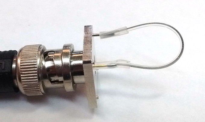
In our study of the ideal antenna shape for telemetry reception, we found that a full-wavelength loop had the best omnidirectional behavior. Their omnidirectionality is further improved if we stop them from resonating by adding an attenuator to the base of the loop. This attenuator also serves to stop radio-frequency oscillations that might otherwise arise in the antenna cable. The attenuator greatly improves the performance of the antenna in highly reflective environments such as Faraday enclosures. See the Impedance Matching section below for measurements.
[10-MAR-25] The following versions of the A3015 exist.
| Version | Name | Description |
|---|---|---|
| A3015A | Undamped Loop Antenna | 320-mm wire loop with stand, discontinued |
| A3015B | Damped Loop Antenna | 320-mm wire loop with stand, active |
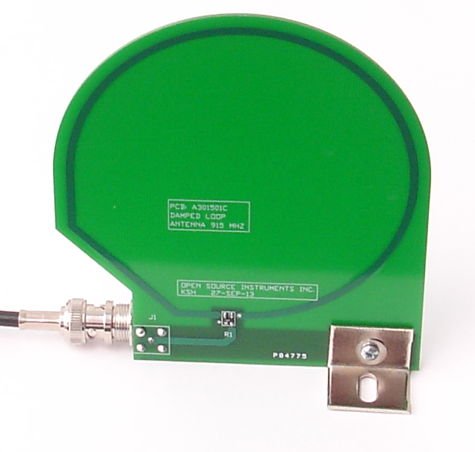
| A3015C | Damped Loop Antenna | 320-mm copper trace with stand, active |
| A3015D | Aquatic Loop Antenna | 50-mm wire loop with connector, active |
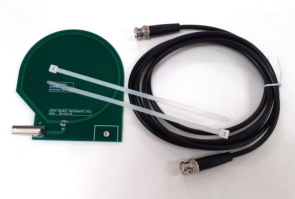
| A3015E | Damped Loop Antenna | 320-mm copper trace with zip-ties, active |
The A3015A and A3015B are obsolete. Undamped antennas, such as the A3015A and A3015D, do not perform well in Faraday enclosures, as we describe below.
[10-MAR-25] Different antenna shapes are sensitive in different directions and to different polarizations of the incoming radio-frequency wave. Their behavior is also affected by their interaction with the cable and the circuit at the other end of the cable. Long cables attenuate the signal. Short cables carry reflections back from the other end. A perfect match between the cable and antenna makes the antenna more sensitive in some directions, but less sensitive in others. For robust reception of telemetry signals from freely-moving animals, we try to increase the minimum efficiency of the antenna, so that the antenna will have no blind spots. For measurements of reception from live animals and test sources, see our Reception Page.
S3015_1.gif: Antenna circuit diagram showing connector, attenuator, and layout.[12-MAR-22] The following table summarizes the properties of common coaxial cables. We use pre-assembled RG58C/U cables with BNC connectors, purchased from L-com. Their RG58C/U data sheet is here. When we tried cut-price coaxial cables, we found their attenuition to be three times higher than the RG58C/U specification requires.
| Type | Impedance (Ω) |
Diameter (mm) |
A 100 MHz (dB/m) |
A 900 MHz (dB/m) |
A 2400 MHz (dB/m) |
Comment |
|---|---|---|---|---|---|---|
| RG-58/U | 50 | 5.0 | 0.11 | 0.34 | 0.61 | Solid Conductor |
| RG-58A/U | 50 | 5.0 | 0.18 | 0.70 | 1.3 | Stranded Sn-Coated Conductor |
| RG58C/U | 50 | 5.0 | 0.16 | 0.67 | 1.2 | Stranded Sn-Coated Conductor |
| RG-59/U | 75 | 5.9 | 0.08 | 0.25 | 0.40 | Solid Conductor |
| RG-59B/U | 75 | 5.9 | 0.11 | 0.37 | 0.65 | Cu-Coated Steel Conductor |
| RG-213/U | 50 | 10 | 0.06 | 0.25 | 0.46 | Stranded Conductor |
| RG-214/U | 50 | 10 | 0.06 | 0.25 | 0.46 | Double-Shielded Stranded Ag-Coated Conductor |
| RG-142B/U | 50 | 5.0 | 0.10 | 0.4 | 0.7 | Double-ShieldedTeflon Dielectric Solid Ag-Coated Conductor |
| RG-223/U | 50 | 5.4 | 0.13 | 0.45 | 0.8 | Double-Shielded Solid Ag-Coated Conductor |
| RG-174/U | 50 | 2.8 | 0.30 | 0.94 | 2.5 | Stranded Conductor |
Our older laboratory BNC cables are RG-58A/U. As shown in the table above, these cables attenuate by 0.7 dB/m. A 1-m antenna cable gives us plenty of opportunity to place the antenna between two animal cages. Nevertheless, we ordered some longer RG-213/U cables, and compared their performance to those of RG-58A/U cables.
We used the same power-measurement apparatus we describe in our RF Combo Manual to measure the attenuation of cables. Our source of RF was −4 dBm at 910 MHz, provided by an A3016MT. We connected this source of power to the RF input of a ZAD-11 mixer with our test cable. For our LO we used a +10 dBm 864 MHz A3016SO. The IF amplitude and power are given below. For the raw data, download this.
There must be more than just attenuation taking place in the cables. Our IF power is lower for our 12-inch RG58C/U cable than it is for our 36-inch RG58C/U cable, and almost equal at lengths 12 inches and 132 inches.
Nevertheless, we conclude that we can expect a power loss of no more than 3 dB as a result of inserting a 96-inch RG58C/U cable between the mixer and the antenna. Given the flexibility and range of the 96-inch cable, and the small power loss, we see no reason to use a shorter cable with the A3015.
[10-MAR-25] The coaxial cable we use to connect the antenna to our receiver or transmitter circuit presents its own impedance to the antenna. The most common values for coaxial cable impedance are 50 Ω and 75 Ω. If we know the polarization of our incoming signal, and the signal is weak, we benefit from matching our antenna and cable impedance closely. The close match allows us to extract more power from the antenna, or deliver more power to it. But if we do not know the polarization of the incoming signal, a poor imedance match makes the antenna less discriminating. It's maximum sensitivity drops, but its minimum sensitivity rises. In the case of loop antennas, such as the A3015A or A3015B, the mis-match between the cable and antenna dampens the asymmetric resonance of the loop in the vertical direction, which would otherwise render the loop insensitive to horizontally-polarized waves. We present measurements of the maximum and minimum sensitivity of various antennas here.
[10-MAR-25] An antenna combiner takes the signals from several antennas and adds them together to produce one combined antenna signal. Antenna combiners are useful if we have more antennas in our telemetry system than we have antenna inputs on our telemetry receiver. Our original Data Receiver (A3018D) provided only one antenna input, so an antenna combiner was essential for reception from more than one bench-top Faraday enclosure. Our Octal Data Receiver (A3027E provided eight antenn inputs, but some IVC rack systems need sixteen antennas to cover all cages, so dual antenna combiners are deployed to bring all sixteen antenna signals into the receiver. Our latest telemetry receiver, the TCB-B16, provides sixteen independent antenna inputs, and so far, this has proved sufficient for all enclosures. We do not expect antenna combiners to play a part in future telemetry systems, but they remain an essential component in older systems.
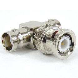
The simplest combiner we can use is a BNC T-junction, like this. It joins two antenna cables together. The T-junction is inexpensive and readily available. But the T-junction has two disadvantages. When we connect two cables together directly, we lose at least half of our signal power. And we can destabilize the antenna amplifier as well, because the signals propagating along the cables reflect from the T-junction. Our Data Receiver (A3018D) has one antenna input, a deficiency of gain, and a tendancy to oscillate. The T-junction combiner does not work well with its antenna amplifier.
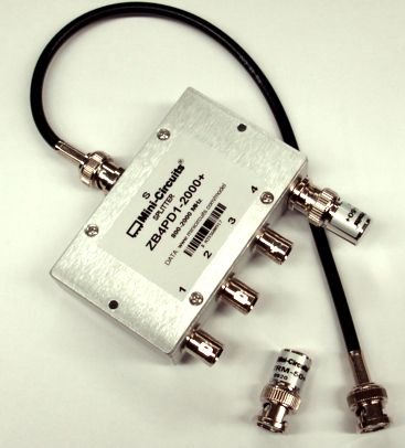
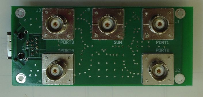
Better than a T-junction is a passive combiner that adds two or more antenna signals together without loss and without reflections. The Antenna Combiner (AC4A) is a four-way combiner made out of a ZB4PD1-2000. The AC4A consists of a four-to-one passive power combiner, two BTRM-50, which are 50-Ω terminators, and a short coaxial cable.
In the early days of our telemetry system's development, we equipped each bench-top faraday enclosure with one centrally-located antenna. We then connected four such antennas to a single receiver input with the AC4A antenna combiner. Or we used a ZAPD-1 to connect two antennas to one receiver input. These passive combiners attenuated our antenna signal less than 1 dB. Nowadays, we place four antennas in each benchtop enclosure and connect each of them to a separate, independent antenna on a sixteen-way receiver.
If we are going to have a circuit combining antenna signals, we can add amplification to the combiner as well, which is shat we did in our discontinued Active Antenna Combiner (A3021B). This device amplifies each of four inputs before adding them with a 4-way passive combiner.
The Octal Data Receiver (A3027) has eight antenna inputs, each of which provides ample gain and is unconditionally stable. We can combine antenna signals with T-junctions and see no significant degradation of reception. We present a comparison of passive, active, and T-junction combiners in the antenna chapter of the A3027 manual. The implication of these tests is that a T-junction joining two antenna cables is just as good as any other combiner, but three T-junctions joining four antenna cables is significantly less effective than an AC4A or A3021B combiner. Thus we should feel free to connect up to 16 antennas to an Octal Data Receiver (A3027) using eight BNC T-junctions.
[10-MAR-25] Using the power-measurement apparatus described above, we mixed 864-MHz LO with 910-MHz RF to obtain a −14 dBm IF signal. We passed the RF signal through a 240-cm cable on the way to the mixer. We unplugged the cable from the RF source and inserted an 80-mm whip antenna into its BNC socket output. We plugged an A3015A Loop Antenna into the free end of the cable that had previously been connected to the RF source. At range 1 m, we observed transmission from the whip antenna to the loop antenna. We rotated the A3015A loop antenna in all directions, and our IF signal varied from −46 dBm to −56 dBm. Transmission and reception across 1 m presents a minimum loss of 32 dB with respect to direct connection. In other words: we receive 0.1% of the power available at the RF source.
We discuss transmission efficiency here. To the first approximation, our loop antenna gathers all RF power that enters its effective aperture. At range 100 cm, the power radiated from our quarter-wave antenna is distributed over a ±45° solid angle perpendicular to its length. This solid angle has surface area roughly ½4π1002cm2 ≈ 60,000 cm2. The effective aperture of a well-terminated loop antenna is roughly equal to its diameter squared, which in the case of our 900-MHz A3015A loop, is 100 cm2. We expect the power loss going from the RF source to the antenna to be roughly −28 dB.
Our loop antenna is not well-terminated. The cable impedance is 50Ω while the its own impedance is 100Ω. We discuss poorly-terminated omni-directional antennas here. Our loop antenna is 3 dB less sensitive in one direction than a well-terminated loop, but 6 dB more sensitive in the perpendicular direction. With our poorly-terminated antenna, we expect the one-meter transmission loss to be −31 dB. We observe −32 dB.
[10-MAR-25] For a presentation of the development of the A3015 antenna family, see its Development Page.